ZOrbiter v2 now supports Revo Six, Revo Rigid (Voron), E3D V6, Dragon HF, Dragon HF Rigid Mount
Please read carefully and do not miss the steps of the tutorial and always read the step description. ZOrbiter v2.0 is very similar to its predecessor. Robert, who is the designer of Orbiter Motors did some improvements with the help of the feedback collected from the community and released v2.0 so did I. Please visit Orbiter Projects for more information about Orbiter development.
The new Orbiter v2 Motor approx. 5mm shorter than v1.5 and slightly lighter. And there are some advantages when printing with soft filaments such as TPU. Please check the Orbiter Projects website for the differences between Orbiter v1.5 and v2.0.
You can download the ZOrbiter Firmware here.
Buy ZOrbiter v2.0 Extruder Kit
Buy ZOrbiter v2.0 Extruder Plastic Parts and Screws Only
Zaribo STL Repository or Printables.com for STL files
Note: Please print the filament sensor lever first and check if your magnet fits in the slot. It shouldn’t be loose. There are two filament sensor levers in the STL repo. One has a 2mm slot, other has a 1.93mm slot for the magnets.
Screws and nuts:
10 x M3x10
6 x M3 Hex Nut
2 x M3x35
11 x Square Nut
1 x M3x25
3 x M3x14
3 x M3x22
ASSEMBLY GUIDE
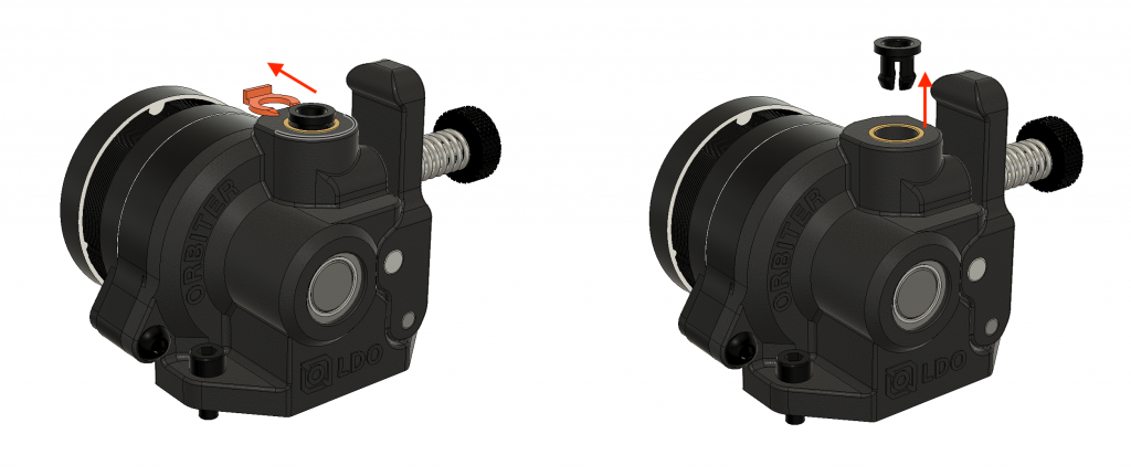
Step 1
Remove the Bowden coupler ring and take out the Bowden coupler.
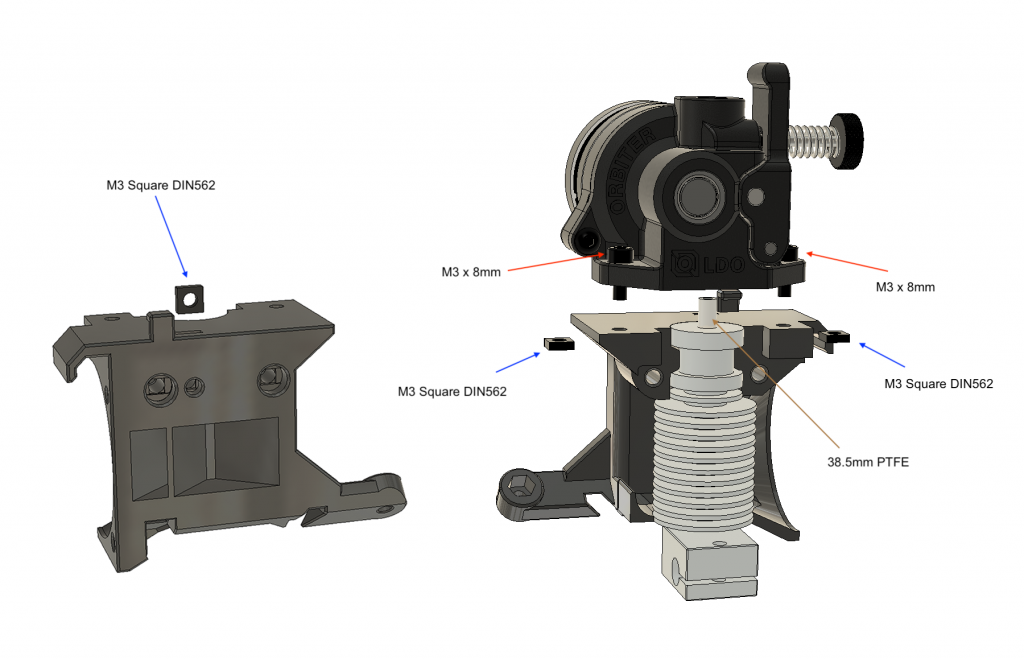
Step 2
Insert a square nut on the extruder cover for the front fan first. Then insert the square nuts on the sides and place the hotend before assembling the motor. Use M3x8mm socket cap screws to mount the Orbiter motor in its place by inserting the PTFE to the bottom metal hole of the motor assembly. 38.5 PTFE is for E3D V6 and Volcano Hotend. (PTFE is 26mm for REVO 6, 29mm for Revo Voron) Please use the PTFE tube cutters for the correct sizes.
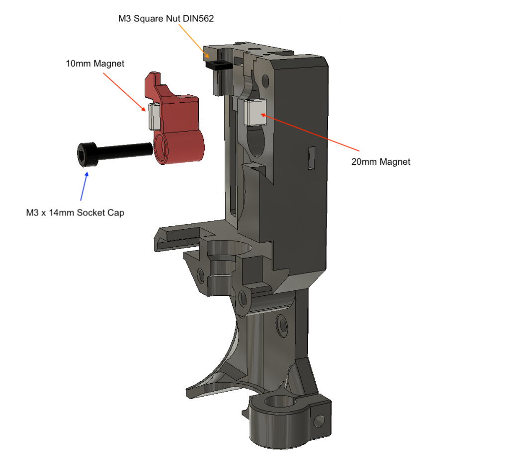
Step 3
Insert the magnets on the Filament Lever and Extruder body. Magnets should repel each other. Insert the Square nut on top of the body for FS Cover Screw. There are two different Filament Sensor Lever files for different magnet thicknesses. One for 2mm magnets the other is for 1.85~
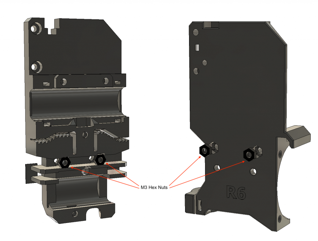
Step 4
Insert M3 hex nuts to their places at the back of the X carriage and Extruder Body. You can use an M3 screw to place and push them more easily.
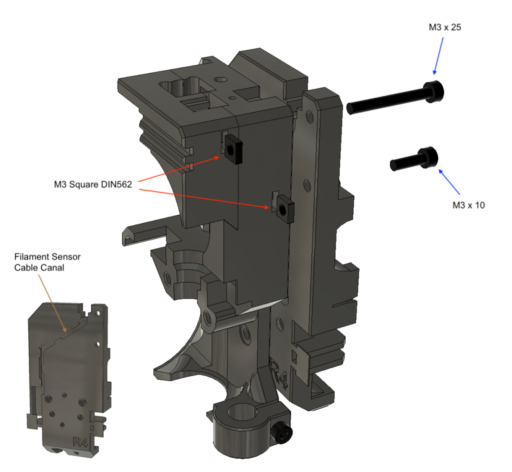
Step 5
First, pass the filament sensor cable through the X Carriage canal. Insert the square nuts and place the front cover on the extruder body. Use M3x25 screw to assemble and fasten X Carriage, Body and front cover parts together. Fasten the M3x10 screw to secure the X carriage on the extruder body.
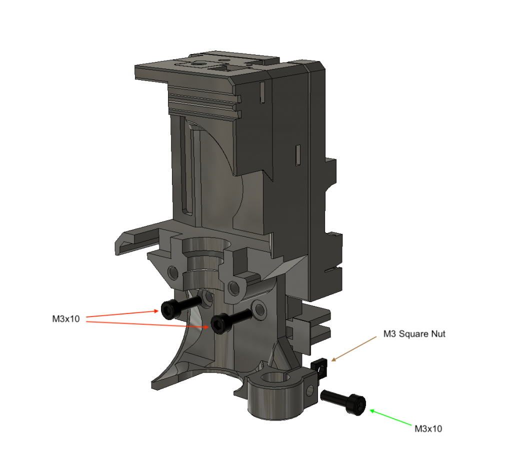
Step 6
Secure the bottom part of the extruder body with two m3 x 10 screws in front. Insert the M3 Square Nut and the M3 x 10 screw to prepare for the PINDA.
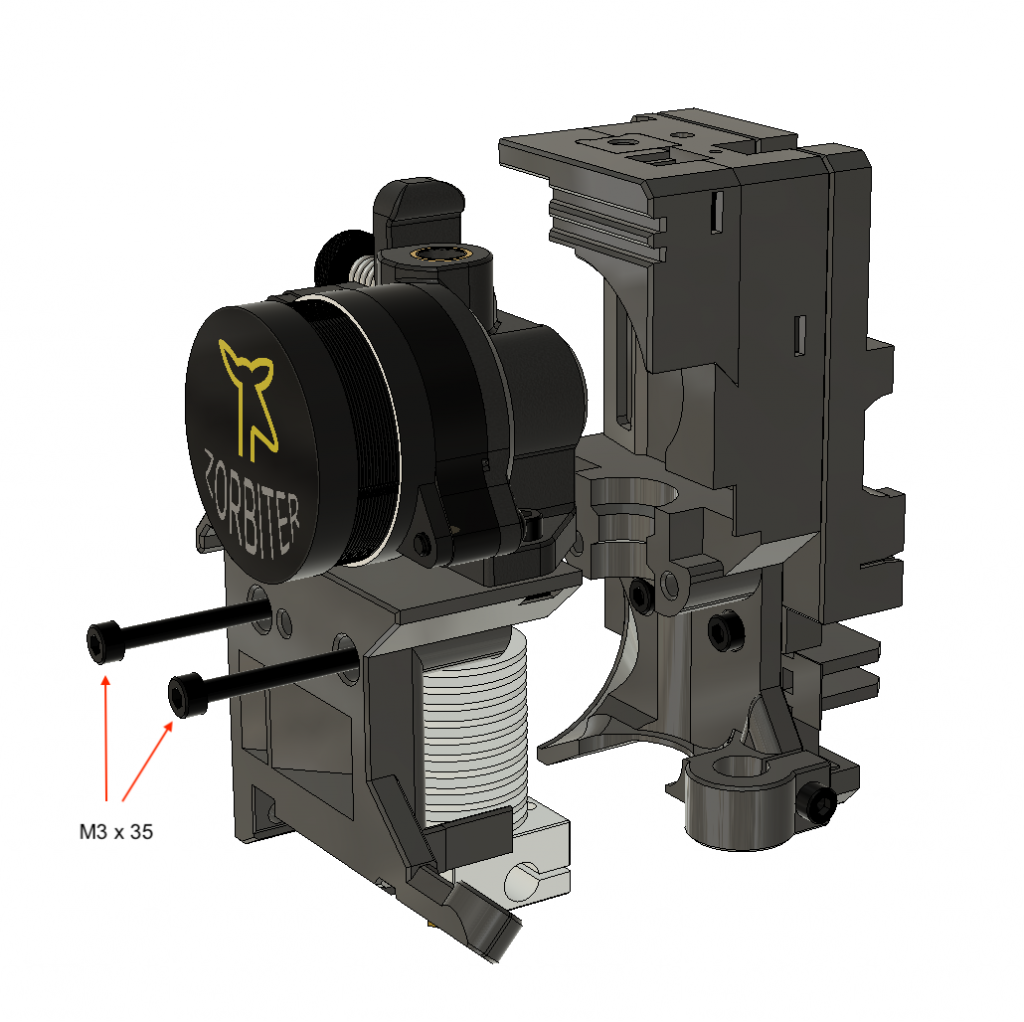
Step 7
Place the motor assembly with hotend into its place at a right angle and tighten M3 x 35 screws. Ensure the hot end is positioned at a right angle while tightening.
Step 8
Insert a square nut into the fan shroud and put it into its place before assembling the fan. And also pass the motor cable behind the jut on the extruder cover and then rearward through the gap above the fan socket. keep the fan cable rearward.
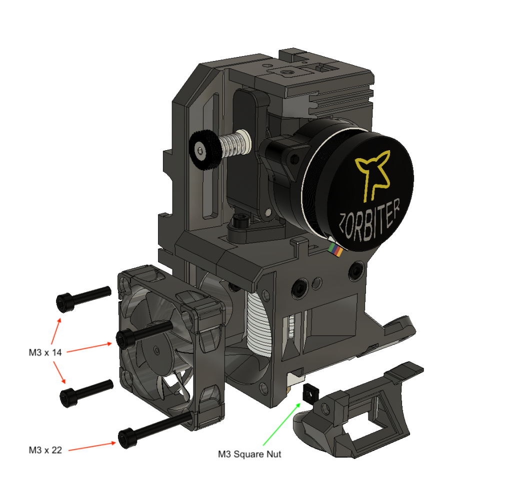
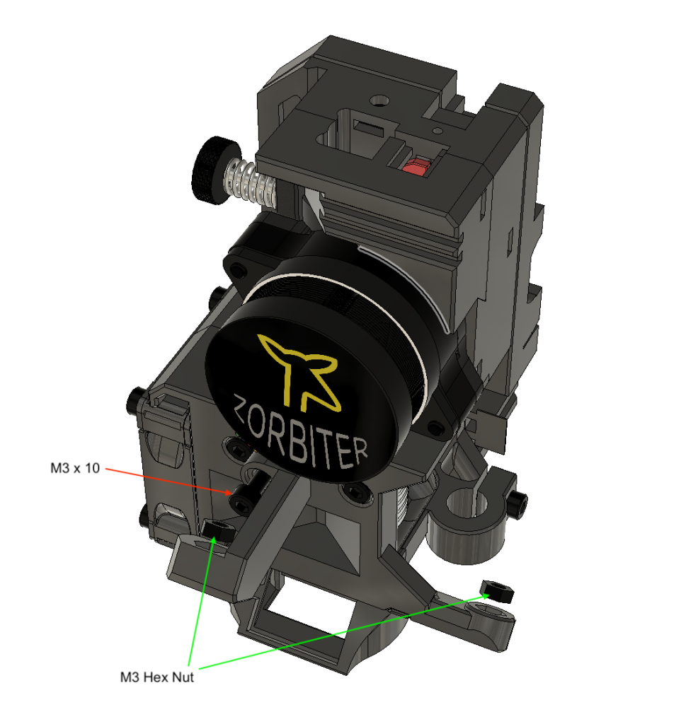
Step 9
Use M3 x 10 screw to mount the print fan arm. Inser two M3 Hex nuts to the holes seen on the picture to be able to mount the print fan.
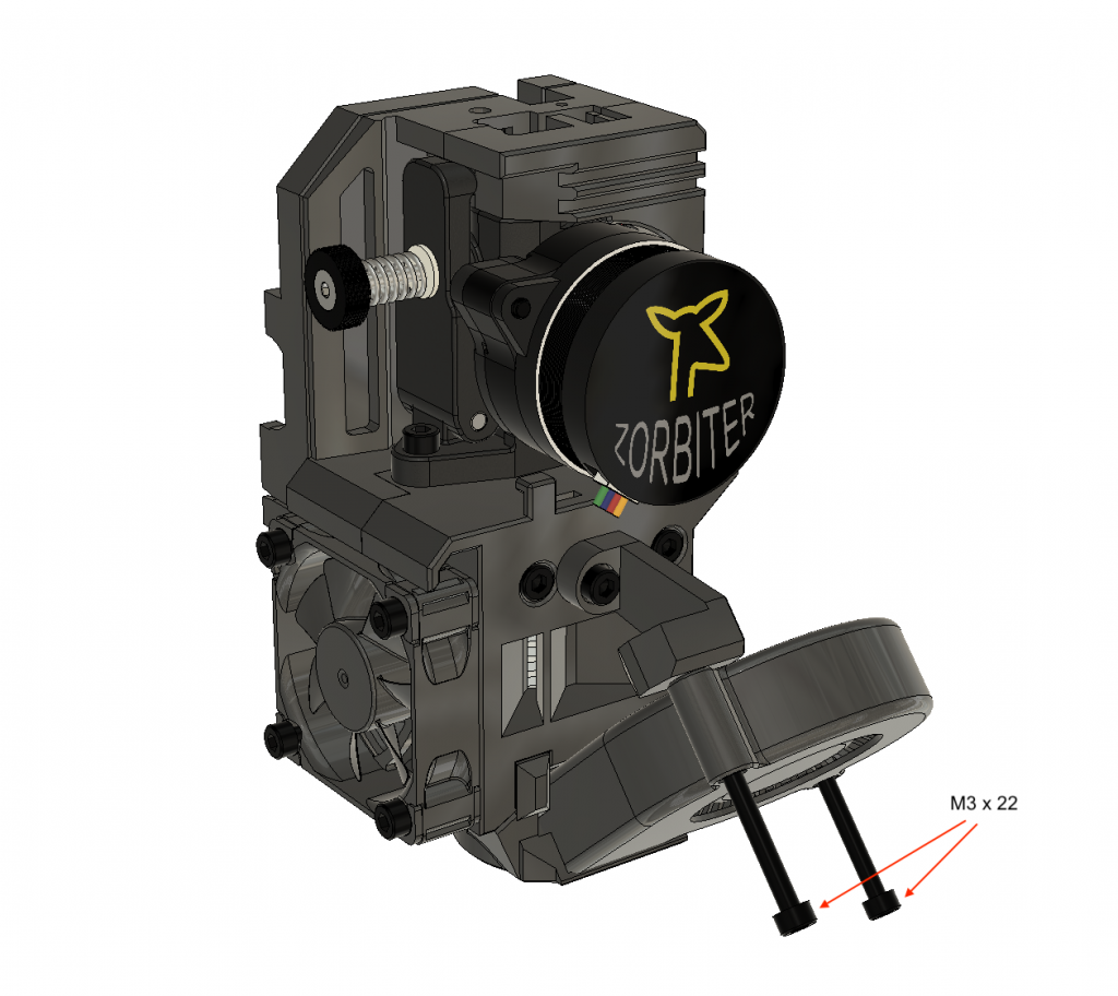
Step 10
Place the print fan as seen in the picture and fix it with two M3 x 22 Screws. Do not overtighten the screws cause you may damage the 5015 fan holes.
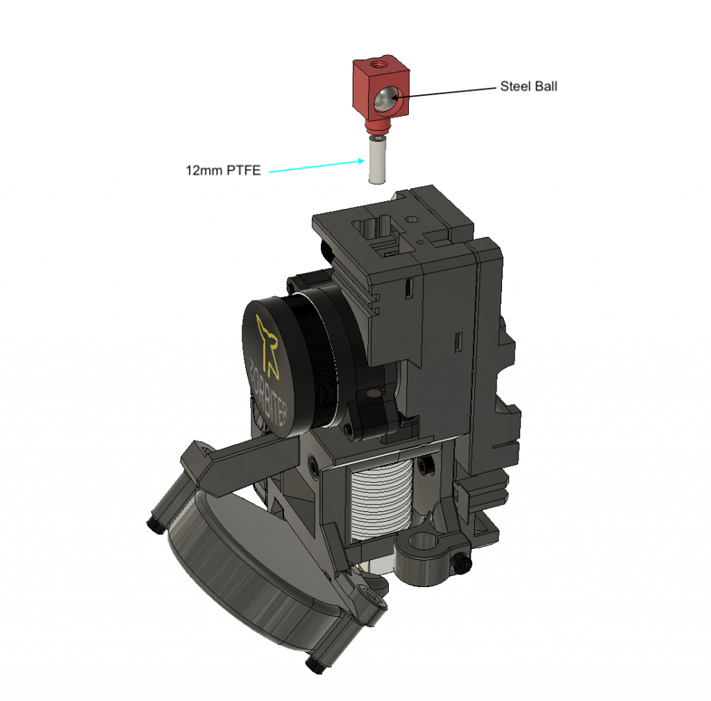
Step 11
Insert the 12mm PTFE tube and steel ball into the housing. Put it into its place, however, it is going to be stuck in the middle of the way due to Filament Sensor Lever. Do not push further and move to the next step.
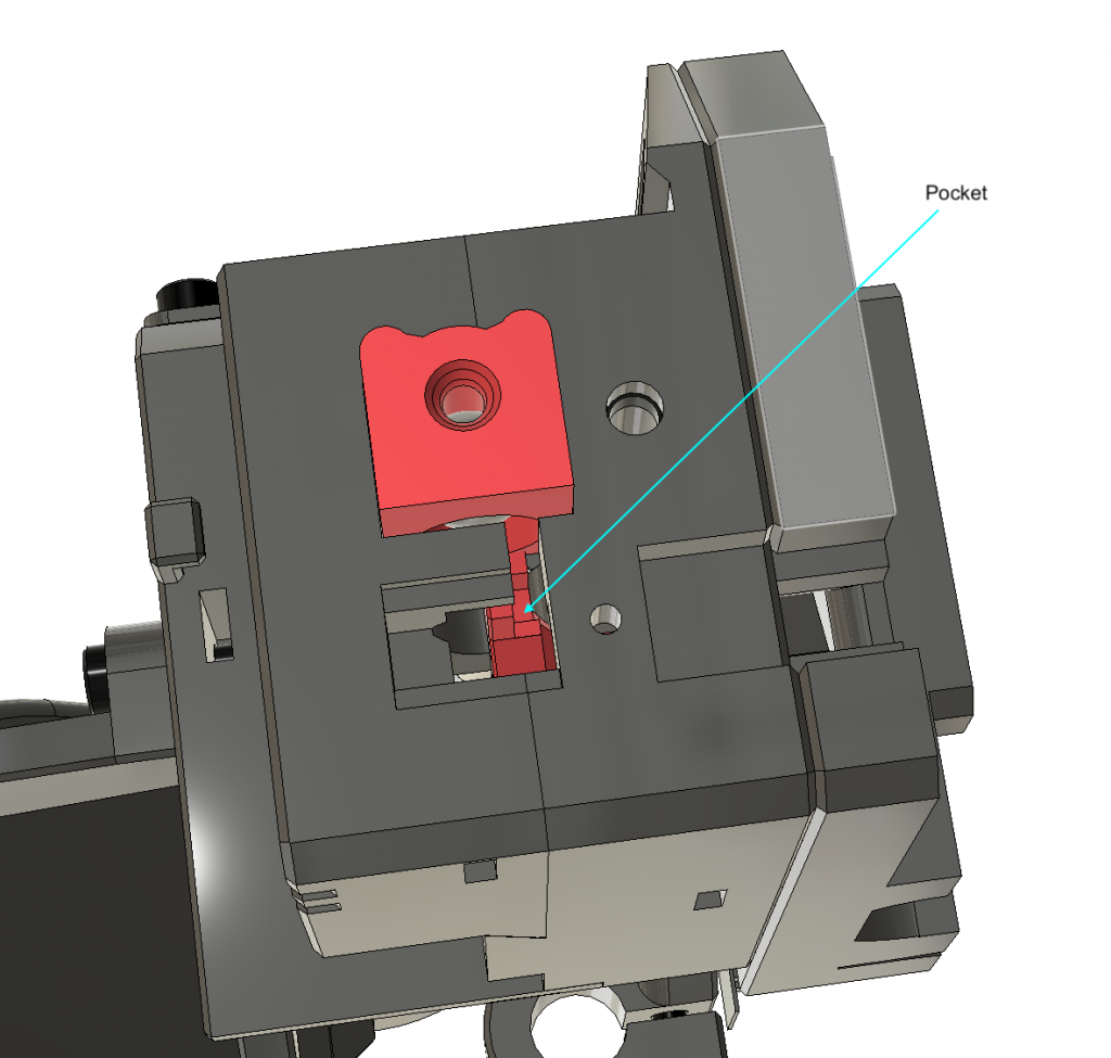
Step 12
Use a small screwdriver or a scriber and pull the filament sensor lever from the pocket shown to push the ball holder down and make it flush with the top
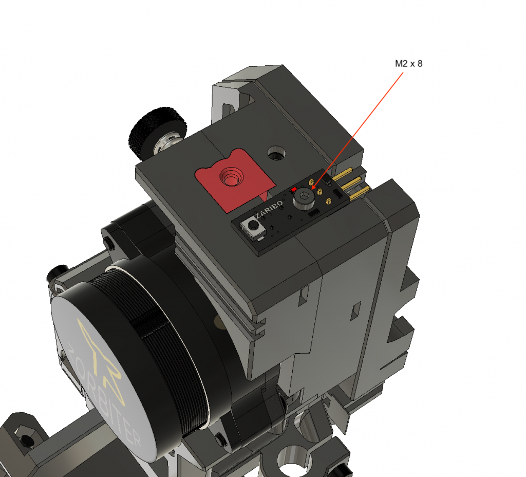
Step 13
Mount the Filament Sensor with an M2 x 8 screw. You can use stock Prusa Filament Sensor as well.
Step 14
Lastly, put the filament sensor cover on top and use an M3 x 10 screw to fix it. For cable management and 3D printer assembly please refer to your printer build manual.

Follow us
We will keep you updated
Will this work with MMU2S or do I need an extra design for the filament sensor?
It will require a filament sensor design on top of it. We will do it soon.
What about the filament sensor? You promised one …
Hi Pete, it has been already done by a community member, please search Printables.com👍
Good news. Hopefully it’ll come very soon …
What about MMU2S sensor? You promised a solution.
Price.?
There are links on top of the blog; you can check them there👍
is it or will it be compatible with the revo micro?
It is not, can you remix it? If you can, we can send you the step files.
Of course 🙂 Please send me the STL files
* step files
Is there any way to change the unload filament length in the firmware? The position of the lever on the side of the extruder makes it difficult to open to pull out the remaining filament.
I use stock firmware, the same as Prusa firmware and I never had an issue with filament unload length. Rarely the filament end stuck somewhere while unloading but it sometimes happened on the stock Prusa extruder too.
the extruder motor runs to slow with the preconfigured firmware.
Hi Matt, please hard reset your Printer, search Prusa mk3 hard reset for the process. Thee EEprom on the board sometimes does not update after flashing.
New filament sensor cover where can i find that??
Please check printables.com